Introduction
Truss and beam structures are fundamental components in civil and structural engineering. They are widely used in buildings, bridges, towers, and industrial structures due to their ability to efficiently carry loads while minimizing material consumption. Understanding their structural behavior, construction principles, materials, and computational design methods is essential for modern computer-aided engineering and building information systems.
Beam structures primarily resist loads through bending, while truss structures transfer forces mainly through axial tension and compression in their members. Both systems are widely analyzed using numerical methods and computer-based simulation techniques.

Materials
The selection of materials significantly affects structural performance and durability. Common materials used in truss and beam structures include:
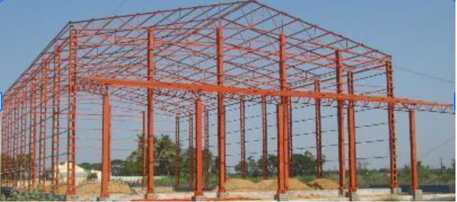
Structural steel
high strength, excellent ductility, and predictable mechanical behavior. Steel is widely used in bridges, industrial buildings, towers, and long-span roof systems. Its high strength-to-weight ratio allows the construction of lightweight yet strong structural frameworks.

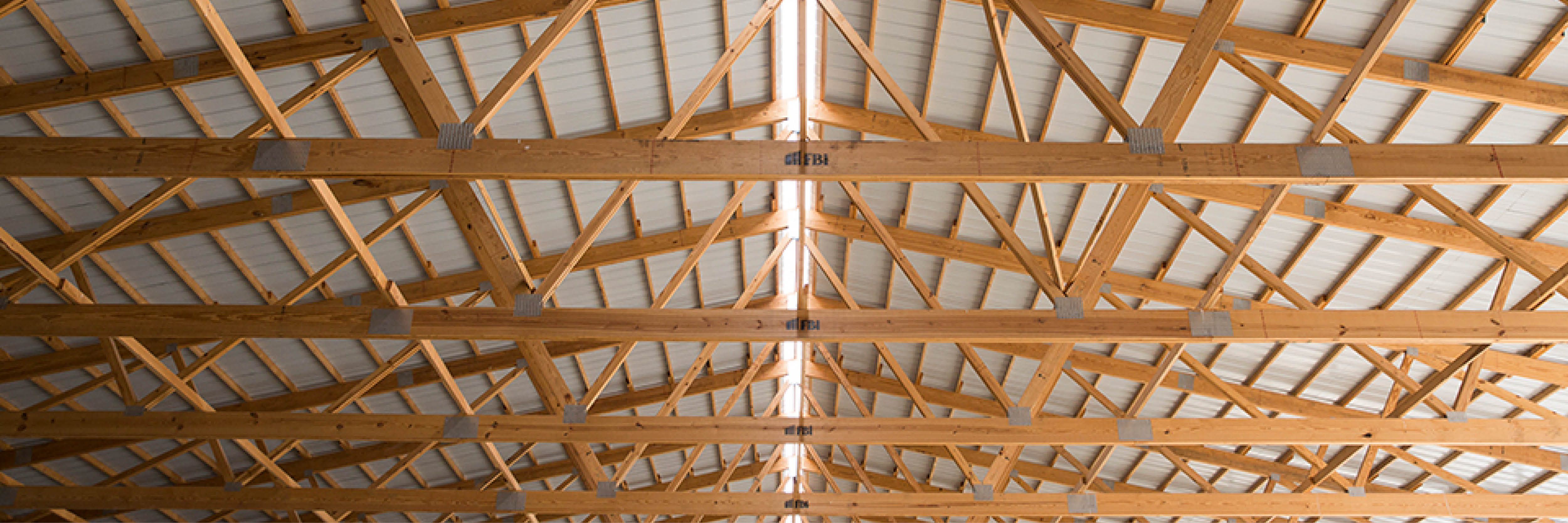
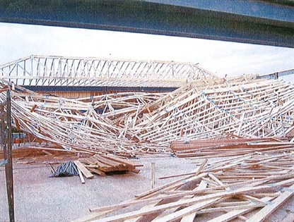
Timber
frequently used in roof trusses for residential and small commercial buildings. Timber structures are relatively lightweight and easy to fabricate. Modern engineered wood products such as glued laminated timber (glulam) and cross-laminated timber (CLT) allow larger spans and improved structural performance.
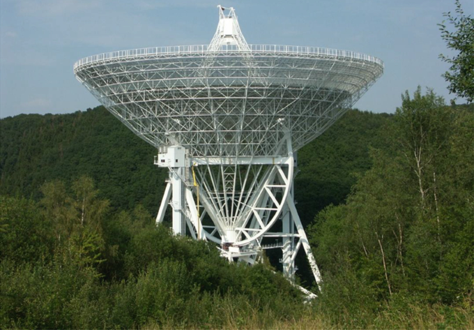
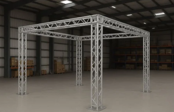
Aluminum
used in lightweight structures where corrosion resistance and reduced weight are important. Aluminum trusses are common in temporary structures, exhibition halls, stage systems, and certain aerospace or specialized engineering applications.
Reinforced or prestressed concrete
less common for traditional truss members due to its lower tensile capacity compared to steel, but sometimes used in specific applications such as large-span bridges or precast structural systems. Prestressing techniques can improve tensile performance and enable longer spans.
Among these materials, steel is the most widely used in truss structures due to its high tensile strength and its ability to efficiently carry both tension and compression forces. Steel members can be manufactured in a wide range of standardized profiles, which simplifies structural analysis, fabrication, and assembly.
Structures
Structural systems can vary significantly in complexity, size, and cost depending on the intended application. When designing beam or truss systems, engineers must consider several important aspects that influence both the structural performance and the feasibility of construction.
Key aspects include:
• Simplicity vs. complexity – Simple structures are easier to analyze, design, and construct. More complex structures may provide better performance or longer spans but typically require advanced analysis and more precise fabrication.
• Size and scale – Structures can range from small roof trusses in residential buildings to very large bridge or stadium structures. Larger spans generally require more careful structural optimization and stronger materials.
• Cost efficiency – Structural design often involves balancing structural performance with economic constraints. Efficient structures minimize material usage while still meeting safety and serviceability requirements.
• Construction and fabrication – Some structures are designed to simplify manufacturing, transportation, and on-site assembly. Modular and repetitive structural elements can significantly reduce construction time and cost.
• Structural reliability and safety – Regardless of size or complexity, all structural systems must meet safety standards and building codes to ensure stability under expected loads and environmental conditions.
In CAD and BIM environments, these aspects can be evaluated during the design process by modeling different structural alternatives and analyzing their performance, material consumption, and constructability.
Design
Structural design is the process of determining the geometry, dimensions, and arrangement of structural elements so that the structure can safely carry the expected loads while remaining efficient and economical. A well-designed structure provides sufficient strength, stability, and durability while minimizing unnecessary material use.
Analysis method
Structural analysis methods are used to determine internal forces, displacements, and stresses in structural systems such as beams and trusses. These methods allow engineers to verify whether a structure can safely support the expected loads and meet design requirements. Over time, structural analysis has evolved from manual graphical and analytical techniques to advanced numerical methods implemented in computer software.
Classical methods
Classical analysis methods were developed before the widespread use of computers and were often performed manually or with graphical constructions. These approaches are still important for understanding the fundamental behavior of structures and for verifying computational results.
• Displacement method – determines unknown forces by first calculating structural displacements and rotations. It forms the basis for many modern numerical approaches used in structural analysis.
• Force method – also known as the method of consistent deformations. Unknown redundant forces are determined by enforcing compatibility of displacements within the structure.
• Ritter method – a sectional method used for analyzing trusses by cutting through selected members and solving equilibrium equations to determine internal forces.
• Clebsch method – an analytical method used for determining internal forces in statically determinate truss systems.
• Cremona method – a graphical technique for truss analysis that uses force diagrams to determine the magnitude and direction of forces in structural members.s
Modern (computer-based) methods
With the development of digital computation, structural analysis has shifted toward numerical methods that can efficiently handle complex geometries, material behavior, and loading conditions. These methods are widely implemented in CAD, BIM, and structural engineering software.
• Finite Element Method (FEM) – the most widely used computational method in structural engineering. The structure is divided into smaller elements connected at nodes, allowing complex systems to be analyzed numerically.
• Boundary Element Method (BEM) – focuses on modeling only the boundaries of a structure rather than the entire volume, which can reduce computational effort for certain types of problems.
• Volume Element Methods – numerical approaches that discretize the full three-dimensional domain of the structure to analyze stresses and material behavior.
• Mesh-free methods – modern numerical techniques that do not rely on a predefined mesh, allowing more flexibility in modeling large deformations or complex geometries.
• Other advanced methods – including multiscale analysis, topology optimization, and hybrid numerical techniques used in advanced computational structural engineering.
Computer methods
Modern structural design relies heavily on computational methods that allow engineers to simulate structural behavior under different loading conditions.
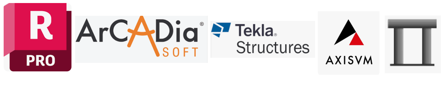
Some of the commonly used software in structural engineering and BIM environments include:
• Robot Structural Analysis Professional
• ArCADia-RAMA
• Tekla Structures
• Dlubal
• Soldis PROJEKTANT
• AxisVM
• RM-WIN
These tools not only perform calculations but also allow engineers to visualize structural behavior, detect potential weak points, and improve collaboration with architects and contractors through BIM integration.
ODE and PDE in Civil Engineering
In modern structural analysis, selecting a specific type of analysis in software such as Robot Structural Analysis corresponds to solving underlying ordinary differential equations (ODEs) or partial differential equations (PDEs) that govern structural behavior.
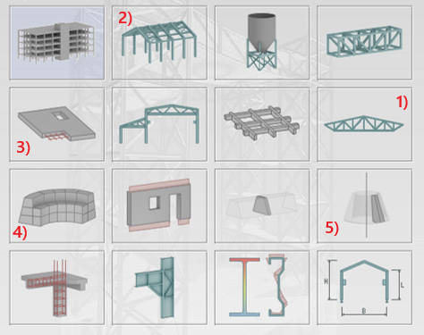
1) Truss Member
$$EA \dfrac{d^2 u}{dx^2} = 0$$Axial deformation along the member; $E$ = Young's modulus, $A$ = cross-sectional area, $u$ = axial displacement.
2) Beam (Euler-Bernoulli)
$$EI \dfrac{d^4 w}{dx^4} = q(x)$$Bending of a beam under transverse load where $E$ = Young's modulus, $I$ = moment of inertia, $w$ = transverse displacement, $q(x)$ = distributed load.
3) Plate (Kirchhoff--Love)
$$D \nabla^4 w(x, y) = q(x, y)$$Thin plate bending under transverse load; $w(x,y)$ = deflection, $D$ = flexural rigidity, $q(x,y)$ = load per unit area.
4) 3D Solid (Lame Equations)
$$\mu \nabla^2 \mathbf{u} + (\lambda + \mu) \nabla (\nabla \cdot \mathbf{u}) + \mathbf{f} = 0$$3D elasticity for isotropic solids; $\mathbf{u}$ = displacement vector, $\lambda, \mu$ = Lamé constants, $\mathbf{f}$ = body force.
5) Axisymmetric Disc
$$D \left( \dfrac{\partial^4 w}{\partial r^4} + \dfrac{2}{r} \dfrac{\partial^3 w}{\partial r^3} - \dfrac{1}{r^2} \dfrac{\partial^2 w}{\partial r^2} + \dfrac{1}{r^3} \dfrac{\partial w}{\partial r} \right) = q(r)$$Radial bending of circular elements; $w(r)$ = radial deflection, $q(r)$ = radial load, $D$ = flexural rigidity.
Analysis vs. Design
In structural engineering, it is important to distinguish between structural analysis and structural design.
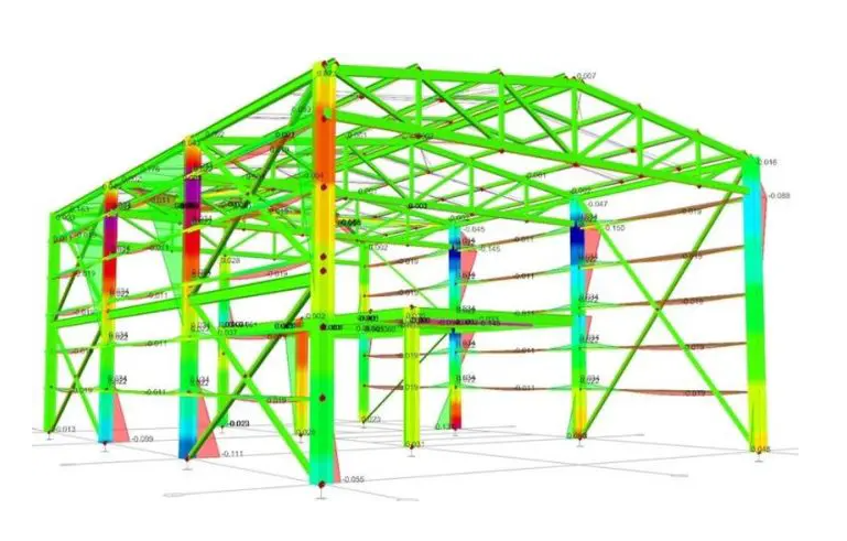
Structural Analysis
Structural Analysis involves determining how a structure responds to loads. This includes calculating internal forces, stresses, strains, and displacements in beams, trusses, plates, and other elements. Analysis is the foundation of engineering decisions: without understanding how a structure behaves under loads, it is impossible to design safe and efficient members.
Structural Design
Structural Design comes after analysis. It involves selecting member sizes, materials, cross-sections, and connections to meet performance, safety, and economic requirements. Design decisions depend entirely on the results of structural analysis: without knowing the stresses and deformations, design cannot proceed reliably.